Designing Custom Airframes for Heavy-Lift UAVs: A Comprehensive Guide
Creating a custom airframe for a large UAV with significant payload capacity is both an art and a science. Whether you’re building a drone for industrial inspections, agricultural mapping, or search-and-rescue missions, a well-engineered frame ensures structural integrity, optimal aerodynamics, and ease of assembly. Drawing on a proven process from Rudra, Edhitha’s flagship UAV for SUAS 2025, here’s a step-by-step walkthrough on how to make a multicopter frame with carbon fiber milled sheets and tubes paired with off-the-shelf components.
1. Define Your Propulsion & Payload Requirements
- - Maximum Takeoff Weight (MTOW): Calculate the total mass including frame, electronics, batteries, and maximum payload.
- - Thrust-to-Weight Target: Aim for a ratio ≥ 2:1 for reliable lift; heavy-lift systems often push toward 3:1 or higher.
- - Motor & Propeller Selection: Research high-efficiency motor/ESC/prop combos rated for your MTOW. Propeller diameter will determine the boom length and influence the design.
2. Starting the Design Process in CAD
Gather 3D models of every onboard component and create models for custom parts. Import all of them into your CAD environment (e.g., SolidWorks, Fusion 360).
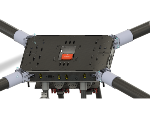
3. Central Frame
The core comprises two carbon fiber plates sandwiching electronics. It must handle high stresses from the booms and landing gear.
- - Base Plate: Houses critical electronics. Use insulation (tape, spacers) to avoid conductivity issues with carbon fiber.
- - Integrates boom mounts, landing gear, and cable management holes.
- - Top Plate: Mirrors the base layout with fasteners and battery slots. A cutout in the center gives access to the flight controller and reduces weight.
- - Use edge interlocking slots to secure side plates without extra fasteners.
4. Side Plate Design
- Made from carbon fiber or 3D printed parts, side plates provide structural support and cable routing.
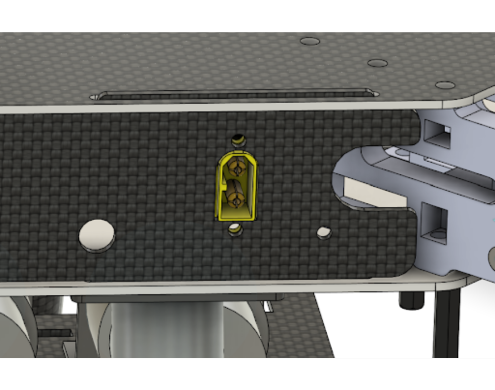
- - Add cutouts for XT60E connectors, auxiliary power, antennas, etc.
5. Additional Layers for Batteries and Other Components
Add spacers to attach extra carbon fiber layers for battery strapping, tanks, or payloads. Bottom-mounted batteries help with weight distribution.
6. Verification, Alignment & Simulations
- - Print the plate drawings to scale and check alignment with real components.
- - Verify connector clearances and cable routes.
- - Static Stress Analysis: Simulate to locate high-stress areas. Use fillets for better stress flow and maintain a minimum FOS of 2.
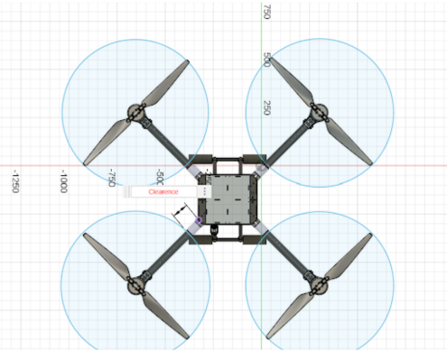
- - Ensure propeller clearance from the central frame (15–20% of prop diameter is a good rule).
7. Prototype Manufacturing & Testing
- - Use cost-effective materials like wood or acrylic for prototypes.
- - Assemble and check for fit, wiring lengths, and CG balance. Many design flaws only emerge during real-world prototyping.
8. Final Revisions & Production Approval
- - Conduct a peer review to catch overlooked issues.
- - Adjust hole tolerances based on manufacturer specs.
- - Use parametric modeling for flexibility during revisions.
By following this structured approach—grounded in rigorous planning, simulated validation, and iterative prototyping—you’ll build a reliable, heavy-lift UAV airframe tailored to your mission’s needs.